Sunday 16 July
Another milestone is reached!
‘i’Beams nearing completion
Next in line after the major reworking on the hulls is the construction and fitment of the crossbeams. They are the very significant structures that hold the whole boat together and turn two separate hulls into a single, beautiful and strong journey boat. Along with the ropes that lash the beams to the hulls, they allow the boat to slightly flex when large loads are applied in heavy seas.
This flexibility provides a more gradual loading of stresses to the structure of the boat as a whole. (Not all catamarans are constructed with this flexible, lashed-beam method. Most modern catamarans are constructed with a rigid connection between the crossbeams and the hulls and this rigidity requires a lot of reinforcing to go with the advanced engineering.)
A secondary benefit of the lashed-beam method is that, if needed, the hulls can be separated and transported on a trailer. Our boat ‘Curious’, has around only 1 ton of weight per hull; heavy to be sure but not-unmanageable when transporting individually on a long road trailer.
Crossbeam Construction
Early February 2017 we started gathering the materials to create the crossbeams;
4 sheets of 3/4 Marine Plywood,
320 linear feet of 1″x 6″ and
160 linear feet 2″x 4″ in 16 foot lengths of Southern Yellow Pine KDAT (Kiln Dried After Treatment),
150 feet of 6″ fiberglass tape
And a butt load of epoxy, fiberglass and filler from RAKA, out of Florida.
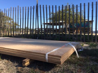
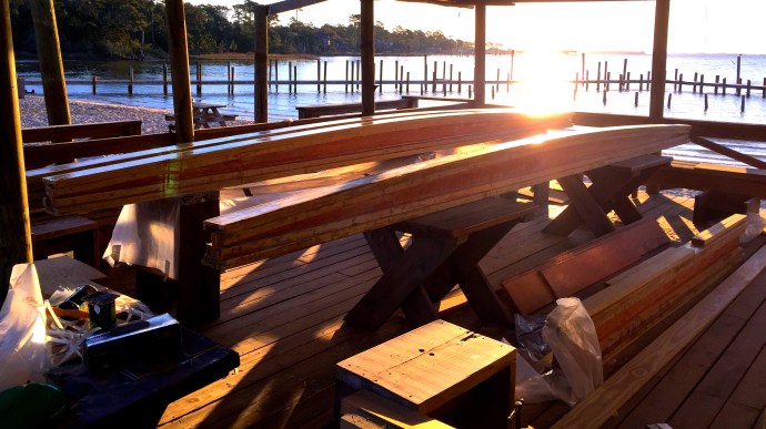
Sheets of Plywood that will become the iBeams

All the pieces needed to tie our boat together
Seeing the piles of lumber, sheets of plywood, glue filler and fiberglass, and trying to envision this mess as the materials that will become one of the most vital components of our boat was intense… and hugely exciting!
Laying out the lines to be cut on the sheets of plywood helped things get into perspective, but then I needed a section of floor that was as flat as possible to ensure that when the gluing starts the beams will be as straight as I could possibly get them.
Now, most of the structures around here at Pirates Cove are anything but flat, straight or square; full of character and personality yes, but not straightness,…nor flatness,…nor squareness, it has a certain Ettamogah Pub feel to it (look it up, it’s an early Australian magazine cartoon series). And so, I needed to shim, shuffle and then shim some more to ensure the frames upon which I would be building the crossbeams were square and true.
Measuring, marking out and cutting.
Marking out the plywood cut lines was a laborious affair. Each width measured, and marked, and then a neighboring sheet of plywood positioned to be used as a straight edge to mark the cut lines. Each piece of plywood had 20 mark out points plus five cut lines…did I mention it was a laborious, drawn out affair? I don’t do well with repetition, my brain starts going to places that have nothing to do with the job at hand; you know like monkeys on the moon or getting a beer at the bar or building an outrigger canoe again. Then I get to the end and wonder if I did it all correctly because I was not paying attention and I need to go back and remeasure all the lines.
Cutting the plywood involved moving one sheet into place on top of another. This time with the sheet edge had to be the correct distance from the cut line so as to be able to run the hand held circular saw along the edge and produce a very accurate cut. Some friends asked “Why not use a table saw?”; well,…I don’t have one. I could have borrowed one but I don’t like using other peoples tools and I’m also a little stubborn.
Each ‘i’ beam uses 6 separate pieces of plywood for the vertical web; 4 pieces 2440 mm (8 feet) long, and 2 pieces 1220 mm (4 feet long). These are arranged on the build frame with two of the 8 foot sections end to end and a 4 footer on the end of that. Laid on top of that arrangement are the remaining three pieces. They are put down so the joins are in the middle of the 8 foot sections; so it’s 8’/8’/4’ and laid on top is 4’/8’/8’, creating really big butt joints… simple huh?
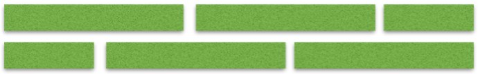
Vertical Web Orientation
When glued together we end up with one piece of plywood that is 6100 mm or 20 feet long and this is the core structure of the beams.
These pieces then need to be cut along the upper edge to give a curved shape to the top of the beam. So out with measuring toys again, marking out from the center, at increasing depths, so the outer ends of the beam webs are less wide than the middle and a long whippy stick is used to provide a nice gradual, fair curve…kind of like a gentle crest of a hill. With the curved lines marked out on each of the vertical webs its time to very carefully cut along those lines.
If you’ve ever heard of the expression in carpentry, “Measure three times, cut once”, well this is a perfect example of why that expression is so important. At this point there is already a weeks worth of effort and hundreds of dollars invested, so to make a simple error like an incorrect reading of the ruler would be a thoroughly heinous event…so I checked the measurement six times and then asked someone else to check it as well, just to be sure.

Top Edge Curve
With the top of the web cut to a fair curve, square pieces of timber (the flanges) need to be attached to the upper and lower edges of the vertical webs to provide side mass and strength to the upper and lower plates of the ‘i’ beam.
To create these square-ish flange pieces I ripped down the center line of the 16 foot 2’x4’s. Now, the flange pieces were 16 feet long and they need to be 20 feet, so a 4 foot piece has to be joined to the ends with what’s called a ‘scarf joint’.

Scarf Joint
A scarf joint is a long tapered joining of two pieces of wood, the taper should be at a ratio in the range of 8:1 to 12:1, this provides a joint strength close of the original timber without any joins. If the wood piece is 1 inch thick you would measure along its length 8 to 12 inches and scribe a line making a long wedge shape, then cut it off. Do the same on the piece to be joined and if the two faces are closely fitted and glued well it will be a nice strong joint…if the two faces are not closely fitted you may have a weak joint and it might just fail and your boat may fall apart, so make the faces of the joint fit together very well.
I glued the first flanges to the lower, straight edge of the webs and then glued and screwed the second flanges to the bend of the upper edge. So now I had a skinny ‘I’ beam.
Flange Positions
The great advantage of being very careful and fastidious with measuring and cutting is that at this point there was very little shaping or truing to be done to keep everything accurate, in line and have good, close fitting gluing surfaces.
Next on the agenda was fitting the upper and lower planks and this was very exciting because this is essentially the end shape of the ‘i’beams.

Top and Bottom Planks
After this a layer of fiberglass is applied to the top to protect from sun and impact damage and I ended up putting a layer on the bottom as well for protection from…something I’m sure.
At this point, the beams get fitted to their positions on the boat, trimmed to size and painted, and as the build continues mounting points for various needs get attached and they become a part of the whole exciting structure.
Here’s a video showing my ‘i’beam construction.